|
SynchroTime
|
|
SynchroTime
|
html ./images/doxygen_badge.svg "Documentation"html ./images/release_badge.svg "releases page"
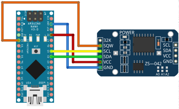
The real-time clock module on the DS3231 chip has proven itself well in work with microcontrollers Arduino, Raspberry Pi, etc. According to the declared specification, it is an extremely accurate RTC with a guaranteed accuracy ±2 ppm (from 0°C to +40°C), which translates into an error of just 1 minute over the course of a year under the worst case scenario. But a large number of modules on the market do not meet the accuracy declared by the manufacturer, which is undoubtedly upsetting. Nevertheless, the manufacturer has provided for the possibility of correcting the drift of the clock time, which is associated with the aging of the oscillator crystal in the range from -12.8 to +12.7 ppm. This correction value can be written to one of the registers on the DS3231 (See part Discussion for exact ppm values). In addition, the manufacturer has provided a the energy-independent flash memory AT24C256 in the module, into which calibration parameters and correction factors can be placed. The tool below can automatically calibrate the DS3231 module.
$ ./synchroTime -h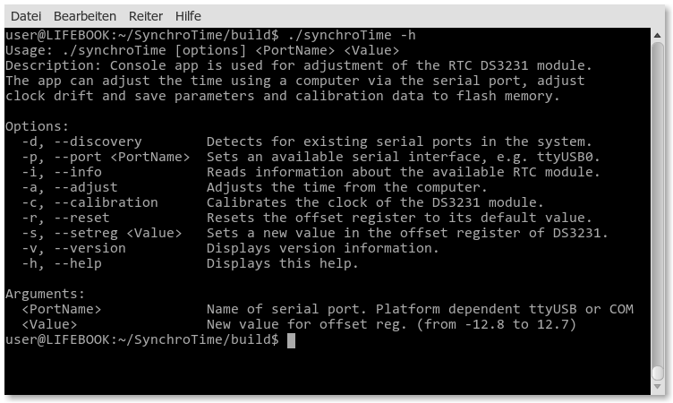
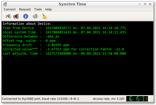
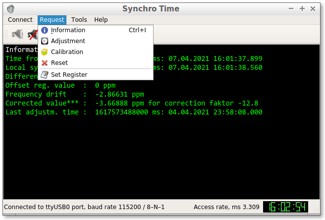
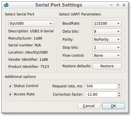
/dev/ttyUSBx, under Windows - COMx). To find the name of this port, call the application with the -d (--discovery) switch: -p \<portName\>. The app will automatically create a configuration file, and the next call will contact the selected port. And under the Windows OS -i (--information) command to get the current information from the DS3231 module. If everything is connected correctly, then you will get the current time of both clocks, the difference between the clocks in milliseconds (with an accuracy of ±2 ms), the value written in the offset register and the calculated time drift value in ppm. If the offset register and time drift are zero, then the DS3231 has not yet been calibrated (see step 5.) -a (--adjust) command. The module clock will be synchronized with the computer time with an accuracy of ±1 ms. After updating the time, the date of the time setting will be recorded in the module's memory, which will allow later to determine the exact drift of the clock time. -c (--calibration) command. For the successful execution of this procedure, the module must be activated (see point 4.) and it is necessary that enough time has passed so that the calculated value of the clock drift is well distinguishable from the rounding error (ca 55 hours or 2.3 days, see part Discussion). The algorithm of the program will calculate the amount of drift of the clock time and the correction factor, which will be written into the offset register. The clock time will also be updated. If the calibration is successful, the current time, drift and correction factor will be displayed, as in the screenshot. -r (--reset) command. The default value will be written to the register, and memory cells will be overwritten with bytes with 0xFF. -s (--setreg) command to add a new value (e.g. -12.8) to the offset register of the DS3231. The new value will be added arithmetically to the old register value. The result will be limited to the values 12.7 and -12.8. Warning: it makes sense to do this operation only in case of resetting all calibration data (see step 6). All functionality is similar to the CLI application (see figure below). As an extra, there is the option of selecting the numerous serial port settings and three features: Status Control, Access Rate and Correction Factor. The Correction Factor is described in detail in the Discussion part. Status Control is an additional functionality to monitor the connection with a device with a Request Rate (from 500 to 10000 ms). The Access Rate feature allows you to display the approximate delay in the exchange of information with the device on the monitor. For the exchange rate of 115200 baud and the exchange of one pair of bytes with the Device, the delay usually should not exceed 3-4ms (depends mainly on the driver used and the HW UART device). Both features can be deactivated.
The computer is a client. The client is always the first to send a request. Upon receipt of each request, the microprocessor must send back the appropriate response.
Each request is as follows: <@ req> <local time> or <value> [CRC], where:
@ - mandatory start byte, sign for the beginning of the transfer (always equal to 0x40, 1 byte),req - request from the set {a, c, i, r, s, t} (size 1 byte),local time - local computer time only for requests a, c, i (size 6 bytes),value - new value for the offset register only for request s (size 4 bytes),CRC - checksum (size 1 byte). The checksum is calculated as the sum of all bytes, starting from the first byte of the request command and ending with the last byte of data,a - time adjustment request,c - calibrating request,i - information request,s - set offset register request,r - reset request,t - status request.| Request Name | Head | Request Data | Size b | Expected response on request |
|---|---|---|---|---|
| Time adjustment | @a | <local time> [CRC] | 2+6+1 | <successful/failed> |
| Calibrating | @c | <local time> [CRC] | 2+6+1 | <old Val> <drift> <new Val> <succ/fail> |
| Information | @i | <local time> [CRC] | 2+6+1 | <RTC time> <Val> <drift> <Last Set time> |
| Set offset Register | @s | <value> [CRC] | 2+4+1 | <successful/failed> |
| Reset | @r | [CRC] | 2+1 | <successful/failed> |
| Status | @t | [CRC] | 2+1 | <successful/failed> |
*: table values offset and jitter, they should be as minimal as possible max|offset ± jitter| <= 10ms. If this is not the case, adjust the configuration file /etc/ntp.conf in which you enter the local time servers.W32tm Time Service synchronizes time once a week, which is not enough for fine tuning and calibration. The optimal solution for OS Windows would be to install a new NTP time synchronization system service to replace the default W32Time service. As an example, you can use one of the advanced projects: NTP for Windows.DS3231 is an extremely accurate RTC with a guaranteed accuracy of 2 ppm (from 0°C to +40°C), which translates into an error of just 60 seconds over the course of a year under the worst case scenario.
While by default DS3231 is already very accurate, we can push its accuracy even higher by adjusting its aging offset register (8bit). This adjustment works by adding or subtracting the corresponding capacitance to or from the oscillator capacitor array. The adjustable range is represented as 2’s complement (-128 to 127) and each LSB change corresponds to ca 0.1 ppm of change in frequency (which translates into roughly between 0.002 to 0.003 Hz). So the overall adjustment range can be achieved programmatically is ca ±13 ppm.
In its default configuration, the TCXO frequency is adjusted every 64 seconds depending on the environmental temperature by switching in or switching out capacitance via an internal look-up table. By utilizing the aging register, we can further null out any remaining offset. The aging offset adjustment is independent of the automatic adjustment via temperature compensation.
The aging offset register is at address 0x10 and the valid values for the input parameter offset ranges from -128 to 127. By default, the offset value is 0.
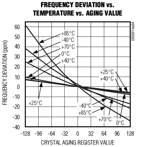
Manipulation with the Aging Register within LBS values affects the thermal stabilization of the oscillator. This is reflected in the graph from the DS3231 datasheet below. According to the curves of the dependences of Frequency Deviation on Temperature and LBS Values, it is seen that there is a stability interval where frequency deviation remains quite stable. This range is between 0°C and +40°C. And according to the datasheet, at room temperature +25°C for each LSB change Aging Register corresponds approximately 0.1ppm Frequency Deviation (i.e. 1 ≈ 0.1ppm). We use this data in our further calculations.
⚠️ Please note that this will limit the operating temperature range!
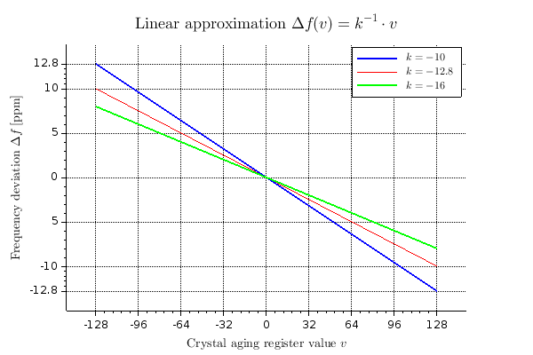
Having a graph of the dependence of the Oscillator Frequency Deviation on the Aging Register Values, the user can independently enter the correction factor k into the calculation. By choosing this factor in an appropriate way, you can get a better approximation for calculating the new value of the Aging register v from the frequency deviation Δf, i.e.
which will be displayed in the parameter list under the name: Corrected value***. The last value can be entered into the Aging register manually, via Request: Set Register <v>.
A graph showing the approximate dependence of the Frequency Deviation on the Aging Register Values is presented below:
For the detailed API documentation, see link. Documentation is produced by doxygen.
| Name | Version | Comment |
|---|---|---|
| Qt lib 32bit | >= 5.5.1 | Didn't test with older versions, but it may work |
| Qt lib 64bit | >= 5.6 | Didn't test with older versions, but it may work |
| C++ compiler | supporting C++11 (i.e. gcc 4.6+) | |
| Arduino IDE | >= 1.8.13 | !Replace compilation flags from -Os to -O2 |
| RTC library | >= 1.12.5 | Adafruit RTC library for Arduino RTClib |
sudo apt-get install build-essential qt5-default qt5-qmake gdb gitgit clone https://github.com/SergejBre/SynchroTime.gitcd ./SynchroTimeQT_SELECT=5 qmake SynchroTime.promake && make cleanSynchroTime is licensed under [
](LICENSE)
 1.8.11

